WORK FOR THE DAYS FROM THE 20th TO THE 29th OF MAY
This week you are going to learn how to use a new component: an RGB-LED (a special type of LED that can emit red, green and blue light). You've got 5 exercises after the explanation that you should share with your technology teacher by email.
If you have any problem or question send an email to ivan.carbajo.profesor@gmail.com
________________________________________________
An RGB-LED is basically three LEDs in one. However, RGB-LEDs do not have 6 terminals, as you may think. In fact, they just have four terminals. The reason is that the three negative terminals are shared and together in just one terminal.
In the images bellow you can see a real RGB-LED (left), and a picture that explains which terminal corresponds each LED in the Tinkercad simulator (right): red LED (number 1), blue LED (number 3), green LED (number 4) and GND for the three LEDs (number 2).

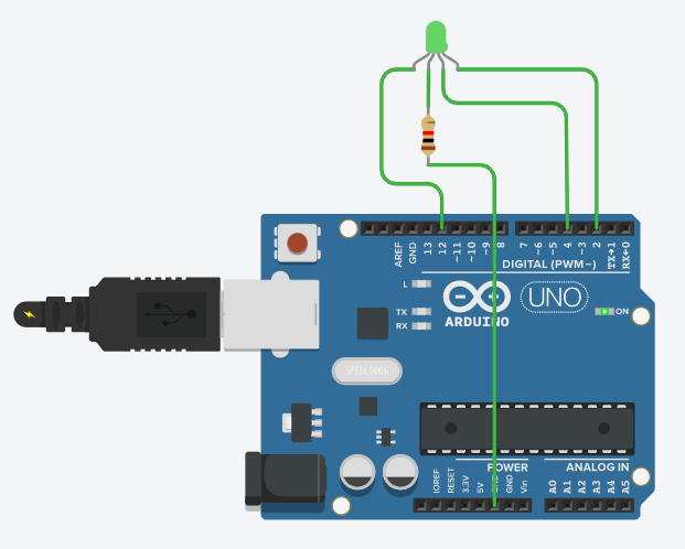
So, imagine you want to control the red LED with pin number number 12, the blue LED with pin number 4 and the green LED with pin number 2. This would be a possible connection:

Remember, to find a component you just need to write its name in the browser on the right:

You won't need to learn any new orders to control an RGB-LED because it can be controled with the same orders that you've been using for the simple LEDs.
Imagine you've connected the component as in the picture we've seen before and you just want to make the blue LED blink each second. As the blue color terminal is connected to pin number 4, this would be the program you need:

List of exercises:
Connect the RGB-LED like this:

Exercise 16: make the LED blink each half a second with green light.

Exercise 17: make the LED blink each two seconds with pink light.

Exercise 18: make the LED blink each one and a half seconds with white light.

Exercise 19: make the LED blink one second with red light, then one second with white light and on.

Exercise 20: make the LED blink half a second yellow then stay one second off, then half a second light blue and finally another second off.
 ________________________________________________
________________________________________________
How to connect an RGB-LED to Arduino?
An RGB-LED is basically three LEDs in one. However, RGB-LEDs do not have 6 terminals, as you may think. In fact, they just have four terminals. The reason is that the three negative terminals are shared and together in just one terminal.
In the images bellow you can see a real RGB-LED (left), and a picture that explains which terminal corresponds each LED in the Tinkercad simulator (right): red LED (number 1), blue LED (number 3), green LED (number 4) and GND for the three LEDs (number 2).

So, imagine you want to control the red LED with pin number number 12, the blue LED with pin number 4 and the green LED with pin number 2. This would be a possible connection:

Remember, to find a component you just need to write its name in the browser on the right:

Don't forget to connect one resistor to protect the RGB-LED as we've done with the simple LEDs before. As I told you, the resistor can be connected to any of the terminals. That's why, in this case, the easiest way to do it is connect it to the negative terminal (the one that must be connected to the GND pin) as it has been done in the picture. otherwise, you would need to use three resistors, one for each of the colours.
How to control an RGB-LED?
You won't need to learn any new orders to control an RGB-LED because it can be controled with the same orders that you've been using for the simple LEDs.
Imagine you've connected the component as in the picture we've seen before and you just want to make the blue LED blink each second. As the blue color terminal is connected to pin number 4, this would be the program you need:

List of exercises:
Connect the RGB-LED like this:
- Red LED to pin number 12.
- Blue LED to pin number 4.
- Green LED to pin number 2.
- Negative terminal to any of the GND pins.
Then do the following exercise having in mind that if you turn more than one colour on at the same time the result will be a mixture of both colours, as you can see in the picture bellow:
Exercise 17: make the LED blink each two seconds with pink light.

Exercise 18: make the LED blink each one and a half seconds with white light.

Exercise 19: make the LED blink one second with red light, then one second with white light and on.

Exercise 20: make the LED blink half a second yellow then stay one second off, then half a second light blue and finally another second off.

This week you are going to learn how to use a new component called servomotor. You've got 4 exercises after the explanation that you should share with your technology teacher by email.
If you have any problem or question send an email to ivan.carbajo.profesor@gmail.com
________________________________________________
A servomotor is a special kind of motor that can be moved to a certain position or angle. They are used, for example, to make robotic arms in which common motors are not useful.

How to connect a servomotor to Arduino?
As it is shown in the image, servomotors have three wires:
a) Brown or black: that must be connected to a GND pin (negative pole of the battery.
b) Red: that must be connected to th 5V pin (positive pole of the battery).
c) Orange or white: that must be connected to a digital pin with the ~ symbol. It is necessary to use one of those pins because those are the only ones that allow to write (send) several values of electric current (from 0 to 180) instead of just ON/OFF (HIGH/LOW). This will be used to select the angle to which the shaft of the motor is going to move.

How to control the servomotor?
The following program is an example in which a servomotor whose orange wire is connected to pin 9 moves from the angle 0º to 90º and back again once and again every 2 seconds.
The following program is an example in which a servomotor whose orange wire is connected to pin 9 moves from the angle 0º to 90º and back again once and again every 2 seconds.

And this is the result:

Explanation of the program:
#include <Servo.h>: you need to write this line at the beginning as it is necessary for the program to work. It must be writen at the begining of any Arduino program that is going to use a servomotor.
Servo john: in this line we are giving a name to the servomotor (in this case I've called it john, buth it could be any other word or letter). From this line on this will be the name used to refer to the servomotor.
john.attach(9): this line must be writen for the board (Arduino) to know the pin in which the servomotor is going to be connected, in this case number 9.
john.write(number from 0 to 180): this is the order that allows to move the servomotor to a certain angle. You just need to write the angle to which the shaft must move between the parenthesis.
delay(2000): wait for a while (2 seconds in this case).
Here you can find the Tinkercad project: https://www.tinkercad.com/things/56GL318CtKf
_________________________________________________________________________________
Here you can find the Tinkercad project: https://www.tinkercad.com/things/56GL318CtKf
_________________________________________________________________________________
List of exercises:
Exercise 12: Make a servomotor connected to pin 6 move from 0º to 90º each three seconds once and again.
Exercise 13: Make a servomotor connected to pin 3 move from 0º to 180º in 10 steps (18º, 36º, 54º, 72º...), and then back to 0º at once. Wait half a second between each of the movements.
Exercise 14: The same than the previous exercise but before the shaft of the servomotor goes back to 0º an LED connected to pin number 12 turns on for 1 second.
Exercise 15: Make a servomotor connected to pin number 5 move (aproximately) from 60º to 100º every 2 seconds. Connect an LED to pin number 4 that turns on for one and a half seconds when the shaft of the servomotor is at 60º.
_________________________________________________________________________
During this week those of you who have alredy sent me the first 10 exercises will have just one exercise to do. Again, the orders you need to know are exactly the same that we have used before. In fact, this new exercise is very similar to exercise number 20, but using 3 LEDs instead of 2.
Exercise 11: connect 3 LEDs like in the gif bellow and make them blink alternately every second.

The reason why I'm only asking you to do one exercise is that I want those of you who still have not sent me all the programs to do it along this week. I'll send a message to each of you in order to remind you what exercises you still haven't done.
Don't forget, try to send all your exercises in the same email (in case you have more than one program to send me) and indicating the number of the exercise to this adress: ivan.carbajo.profesor@gmail.com
_________________________________________________________________________________
_________________________________________________________________________________
WORK FOR THE DAYS FROM THE 14th TO THE 20th OF APRIL
This week you will continue making some programs with the Arduino simulator of Tinkercad. The death line is the 20th of april (included). If you haven't sent the first five exercises you shoul do it as soon as possible.
The components you are going to need are exactly the same that for the previous exercises: LEDs, resistors and an Arduino Uno R3 board. The only difference is that now you are going to control more than one LED in the same program.
The components you are going to need are exactly the same that for the previous exercises: LEDs, resistors and an Arduino Uno R3 board. The only difference is that now you are going to control more than one LED in the same program.
You should review the instructions of the first five exercises before trying to do the new exercises. The three orders you need to know are the same that you've used for the previous exercises: turn an LED on, turn and LED off and wait some time.
Example: imagine you want to make two LEDs, one connected to pin number 3 and another one connected to pin number 9, blink each 2 seconds (2000 milliseconds). This is the program that allows you to do so:

You can play the simulation in this link: https://www.tinkercad.com/things/gbQS3S1XG8J-brave-esboo/editel?sharecode=ypxNM7mu97x3YjqEo65-o7ghzp4AS8OukPW6cAr-ad8
________________________________________________
List of exercises (if you have any problem let me know by email):
Exercise 6: Connect a red LED to pin number 5 and a blue LED to pin number 10 (as in the picture). Make both of them blink at the same time, one second on and one second off.


Exercise 7: With the same two LEDs connected in the same way make both of them blink four times at the same time (half a second on and half a second off), then wait 2 seconds with both of them off.
Exercise 8: With the same two LEDs connected in the same way make both of them blink at the same time (one second on and two second off), then wait 2 seconds with both of them on. After that make them blink at the same time (two seconds on and one second off), then wait 2 seconds with both of them off.
Exercise 9: With the same two LEDs connected in the same way make the blue LED blinks twice (one second on and one off) while the red LED remains off. After that the blue LED turns off and the red LED blinks twice (one second on and one off).
Exercise 10: With the same two LEDs connected in the same way make them blink, two seconds on and two seconds off, but this time alternately (when one LED is on the other one is off, and the other way around.
________________________________________________
How to send the exercises?
Enter the project you want to send and click in Share:

Then in Invite people:

And click in Copy to copy the link:

Finally paste the link in the email. Send only one message with the 5 links in it to make the teacher's job easier to ivan.carbajo.profesor@gmail.com.
________________________________________________WORK FOR THE DAYS FROM THE 26th OF MARCH TO THE 2nd OF APRIL
We are going to start with the robotics unit using a simulator for Arduino. Arduino is an electronic board that allow us to control electronic components as we'll be explained later.
This is an example of how LEDs can be controled using an Arduino board:
When we go back to class we'll work with real components and Arduino boards. However while we stay at home you are going to use a simulator called Tinkercad (that is also used to to do 3D drawing).
This is an example of how LEDs can be controled using an Arduino board:
When we go back to class we'll work with real components and Arduino boards. However while we stay at home you are going to use a simulator called Tinkercad (that is also used to to do 3D drawing).
The first thing you have to do is to enter Tinkercad, which is the program we are going to use. To do so, click in https://www.tinkercad.com/ and then in Join now (if you are already registered in Tinkercad click in Sign in instead):

Click in Create a personal account:

And finally in Sign in with Google (unless you don't have a gmail account).

Once you've entered Tinkercad click in Circuits:

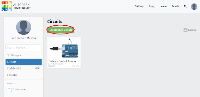
And finally Create new Circuit:

________________________________________________
Then read the following guide slowly (spend at least 15 minutes), it will help you to do the exercises and finally share them with your teacher. The guide has four parts:
1) Parts of an Arduino-Uno board.
2) Parts of an Arduino program.
3) How to configure the pins of Arduino.
4) An example of an Arduino program (LED blinking)
5) The 5 exercises you have to do before easter holidays.
6) Explanation of how to send the exercises to the teacher.
1) Parts of an Arduino-Uno board.
2) Parts of an Arduino program.
3) How to configure the pins of Arduino.
4) An example of an Arduino program (LED blinking)
5) The 5 exercises you have to do before easter holidays.
6) Explanation of how to send the exercises to the teacher.
1) Parts of a microcontroller Arduino-Uno.
A microcontroller is a board that allows to control electronic components according to a program that has prevously been loaded into the board. A program is a group of orders that we give to one or more electronic components.
The microcontroller that we are going to use in class is called Arduino Uno (Arduino is the brand Uno is the model):
The microcontroller that we are going to use in class is called Arduino Uno (Arduino is the brand Uno is the model):
 |
| Real Arduino Uno board. |
Its main parts are:
- The USB Jack: through which the program is loaded into the board.
- The reset button: that if pressed allows to start the program from the begining at any moment.
- The pins, that are the little holes to which the components of the circuit are connected.
There are several kinds of pins that are used for different things, but we are just going to use these ones:
a) Digital pins: are the pins to which we are going to connect the components that we want to control: bulbs, LEDs, motors, buzzers... We'll just use the digital pins from 2 to 13 (see picture).
b) The GND pins work as the negative pole of a battery. There are 3 GND pins in the board (all of them are exactly the same). You will understand what they are used for later on.
c) The 3,3V and the 5V pins work as the positive pole of a battery. You will understand what they are used for later on.
 |
| Parts of an Arduino Uno board. |
2) Parts of an Arduino program.
void setup() {
}
void loop() {
}
A) The setup is the part where we tell the Arduino Board which kind of components we are going to connect in each of the pins. The way in which it is done is explained in the next point (How to configure the pins).
B) The loop is the part where the orders that the different electronic components must follow are written. For example if we want to make a motor rotate, to turn a bulb off, or to make a buzzer sound those orders should be included in the loop of the program.
This part is executed once and again (as in a loop).
________________________________________________________________________
3) How to configure the pins.
Actuators are all those components that transform electric energy into another kind of energy: light, movement, sound... Examples of actuators are: bulbs, LEDs, motors, buzzers...

Sensors are components that can meassure a physical quantity: distance, colour, humidity, luminous intensity, temperature...

IMPORTANT!
If an actuator is going to be connected to a pin the following order must be writen in the setup() of the program:
pinMode(number of the pin,OUTPUT);
If a sensor is going to be connected to a pin the following order must be writen in the setup() of the program:
pinMode(number of the pin,INPUT);
For example if an LED is going to be connected in the pin number 8 and a colour sensor is going to be connected to the pin number 10, the setup of the program should be like this:
 _________________________________________________________________________
For example if an LED is going to be connected in the pin number 8 and a colour sensor is going to be connected to the pin number 10, the setup of the program should be like this:

4) Example of Arduino program with Tinkercad (LED blink, LED que parpadea).
This program makes an LED that is connected to the pin number 9 blink (turn on and off repeatedly) each second (1000 milliseconds).
This program makes an LED that is connected to the pin number 9 blink (turn on and off repeatedly) each second (1000 milliseconds).
First select the components from the menu of the right and drag them to the screen:
 |
| Drag the components from the menu to the screen: one LED, one resistor and one Arduino Uno. |
 |
| Components needed for this program. |
Then connect the components: the LED to the resistor and both of them to pin number 9.
Important: connect the long terminal (the right one) of the LED to the resistor and theother terminal of the resistor to pin number 9. Then connect the short terminal of the LED (the left one) to the GND pin.

Once you've connected the LED you have to write the program to make it blink. First select the buttons Code and Text, as in the picture:

Then write the program:

The three orders we have used for this program are:
- digitalWrite(9,HIGH); (to turn the LED connected to pin 9 on).
- digitalWrite(9,LOW); (to turn the LED connected to pin 9 off).
- delay(1000); (to wait one second (1000 milliseconds)).
And finally click in Start Simulation:

You can check it here: https://www.tinkercad.com/things/7mswgaSbEFy-fantastic-snicket-tumelo/editel?sharecode=G0UHyFvTgvqK796tYNH9DJfNIyqLktQQYAdwZkQ3lPM=
________________________________________________
Exercise 1: Make an LED connected to pin number 5 blink each 2 and a half seconds.
What happens if a motor is connected instead of the LED?

Exercise 2: Make an LED connected to pin number 6 blink each half a second (0,5 seconds).

Exercise 3: Make an LED connected to pin number 3 blink one second on 2 seconds off.

Exercise 4: Make an LED connected to pin number 7 blink faster and faster progressively. First each 4 seconds, then 3, 2.5, 2, 1.5, 1, 0.5, and then back again.

Exercise 5: Make an LED connected to pin number 8 blink slower and slower progressively. First each 0.5 seconds, then 1, 1.5, 2, 2.5, 3, 4, and then back again.

________________________________________________
6) How to send the exercises to your teacher?
Finally paste the link in the email. Send only one message with the 5 links in it to make the teacher's job easier to ivan.carbajo.profesor@gmail.com.
 |
| Example of how to send the exercises by email. |
IMPORTANT!
Once you've finished one exercise you have to go back to the main page clicking in Tinkercad:

And create a new circuit:
________________________________________________
WORK FOR THE DAYS FROM THE 12th TO THE 25th OF MARCH
This term two units will be studied in technology:
1) Robotics: that includes circuit design in breadboards and Arduino programming.
2) 3D printing: with both practical and theoretical aspects about it.
As it is not going to be possible to continue with the unit of robotics while you stay at home, your work for this period will be related to the 3D printing unit. You will investigate to make a presentation about an application of 3D printing that you find specially interesting.
The goals of this project are:
1) To investigate different applications of 3D printing.
2) Make a Power Point (or similar) presentation to explain that application.
Guide for de project:
a) Get information about current 3D printing applications: in medicine, construction, food industry... by viewing the following videos (or others) and searching on the internet.
- Several interesting applications:
2) Choose one interesting application and investigate deeper about ir: for how long it has been used, types of materials used, examples of projects carried out, future improvements of that technique...
3) Make a Power Point (or similar) presentation of at least five slides that include:
- SLIDE 1: Title of the work, name of the student and subject.
- SLIDE 2: List of 3D printing applications (at least six).
- SLIDE 3: Description of the 3D printing application chosen.
- SLIDE 4: Deeper explanation of other aspects of that application.
- SLIDE 5: Future improvements or uses of the technology chosen.
- First: on friday the 20th of march. A presentation with the first three slides.
- Second: the first day of class. The whole presentation.
Evaluation
criteria:
The following
aspects will be considered when grading the project:
- The texts must not be copied directly from the internet.
- The presentation should include images, videos or links to web pages.
- Spelling mistakes will have a negative effect in the mark.
- The originality of the application chosen will also be considered.
This project will of course be considered for the final mark of the term.
If you have any doubt or problem with the activity contact me by email (ivan.carbajo@educa.madrid.org). If you were not able to upload the presentation to Aula Virtual you can also send it to my email indicating your name and the level (2nd of ESO).
UNIT 4: ROBOTICS - ARDUINO
Breadboard connections.
A breadboard is board that is used to insert electronic components to make circuits without the need of soldering the components.

The holes of a breadboard are connected like this:

_________________________________________________________________________________
Value of a resistor.

Example: the resistor of the image is yellow, violet, red and gold. It means its value is: 4700Ω; and has a tolerance of 5%.

_________________________________________________________________________________
Parts of a microcontroller Arduino-Uno.
A microcontroller is a board that allows to control electronic components according to a program that has prevously been loaded into the board. A program is a group of orders that we give to one or more electronic components.
The microcontroller that we are going to use in class is called Arduino:

The microcontroller that we are going to use in class is called Arduino:
Its main parts are:
- The USB Jack: through which the program is loaded into the board.
- The reset button: that if pressed allows to start the program from the begining at any moment.
- The pins, that are the little holes to which the components of the circuit are connected.
There are several kinds of pins that are used for different things, but we are just going to use these ones:
a) Digital pins: are the pins to which we are going to connect the components that we want to control: bulbs, LEDs, motors, buzzers... We'll just use the digital pins from 2 to 13 (see picture).
As you can see some digital pins have the ~ symbol before the number while others do not:
- Pins without ~, that's pins number 2, 4, 7, 8, 12 and 13 can only send two values of electric current: 0 (no current) or 1 (current)
As you can see some digital pins have the ~ symbol before the number while others do not:
- Pins without ~, that's pins number 2, 4, 7, 8, 12 and 13 can only send two values of electric current: 0 (no current) or 1 (current)
- Pins with ~, that's pins number 3, 5, 6, 9, 10 and 11 can send a lot of values of electric current: from 0 to 255.
c) The GND pins work as the negative pole of a battery.
d) The 3,3V and the 5V pins work as the postitive pole of a battery of that voltage.

_________________________________________________________________________
Parts of an Arduino program.
Each time a new Arduino file is opened the following lines appear:void setup() {
}
void loop() {
}
Those are the two main parts of any Arduino program so they can't be deleted.
A) The setup is the part where we tell the Arduino Board which kind of components are we going to connect in each of the pins. The way in which it is done is explained in the next point (How to configure the pins).
B) The loop is the part where the orders that the different electronic components must follow are written. For example if we want to make a motor rotate, to turn a bulb off, or to make a buzzer sound those orders should be included in the loop of the program.
This part is executed once and again (as in a loop).
_________________________________________________________________________
How to configure the pins.
Actuators are all those components that transform electric energy into another kind of energy: light, movement, sound...
Sensors are components that can meassure a phisical quantity: distance, colour, humidity, luminous intensity, temperature...
If an actuator is going to be connected to a pin the following order must be writen in the setup() of the program:
pinMode(number,OUTPUT);
If a sensor is going to be connected to a pin the following order must be writen in the setup() of the program:
pinMode(number,INPUT);
For example if an LED is going to be connected in the pin number 8 and a colour sensor is going to be connected to the pin number 10, the setup of the program should be like this:
For example if an LED is going to be connected in the pin number 8 and a colour sensor is going to be connected to the pin number 10, the setup of the program should be like this:
_________________________________________________________________________
How to control a component connected to a digital pin.
The two orders that must be writen in a program to control any component connected to a digital pin are:
To make the pin send an electric current to the component:
digitalWrite(number,HIGH);
To make it not send an electric current:
digitalWrite(number,LOW);
For example, if we want pin number 5 to send electric current we should write:
digitalWrite(5,HIGH);
If we want the program to remain the same for a certain time the following order must be introduced:
delay(time);
For example, if we want the program to remain the same for 2 seconds we should write:
delay (2000);
Be carefull! The time must be writen in milliseconds (not in seconds!): 1 second = 1000 milliseconds
_________________________________________________________________________
Example of arduino program (LED blink, LED que parpadea).
This program makes an LED that is connected to the pin number 9 blink (turn on and off repeatedly) each second (1000 milliseconds).
First select the components and drag them to the screen:
Then connect an LED (with a resistor in series) to pin number 9.
Important: connect the long terminal (the right one) of the LED to the resistor and then to the pin and the short terminal of the LED to the GND pin.

Once you've connected the LED you have to write the program to make it blink. The three orders we are going to need are:
- digitalWrite(9,HIGH); (to turn the LED connected to pin 9
on).
- digitalWrite(9,LOW); (to turn the LED connected to pin 9 off).
- delay(1000); (to wait one second (1000 milliseconds)).
First select the button code and text, as in the picture:

First select the components and drag them to the screen:
 |
| Electronic components menu. |
|
| Components needed for this program. |
Then connect an LED (with a resistor in series) to pin number 9.
Important: connect the long terminal (the right one) of the LED to the resistor and then to the pin and the short terminal of the LED to the GND pin.
Once you've connected the LED you have to write the program to make it blink. The three orders we are going to need are:
- digitalWrite(9,HIGH); (to turn the LED connected to pin 9
on).
- digitalWrite(9,LOW); (to turn the LED connected to pin 9 off).
- delay(1000); (to wait one second (1000 milliseconds)).
First select the button code and text, as in the picture:
Then write the program:
And finally click in Start simulation:
_________________________________________________________________________
How to repeat an action with the "for" loop.
There is a very abreviated way to repeat an order in Arduino using what is called a for loop.
Imagine you want to make an LED, connected to pin 5, blink four times one second on and one second off, and then four times half a second on and half a second off.
One way to do it would be the following program:
void setup() {
pinMode(5,OUTPUT);
}
void loop() {
digitalWrite(5,HIGH);
delay(1000);
digitalWrite(5,LOW);
delay(1000);
digitalWrite(5,HIGH);
delay(1000);
digitalWrite(5,LOW);
delay(1000);
digitalWrite(5,HIGH);
delay(1000);
digitalWrite(5,LOW);
delay(1000);
digitalWrite(5,HIGH);
delay(500);
digitalWrite(5,LOW);
delay(500);
digitalWrite(5,HIGH);
delay(500);
digitalWrite(5,LOW);
delay(500);
digitalWrite(5,HIGH);
delay(500);
digitalWrite(5,LOW);
delay(500);
}
It is perfectly possible but too long. A shortest way to do exactly the same is:
void setup() {
pinMode(5,OUTPUT);
}
void loop() {
for(int i=0;i<3;i++){
for(int i=0;i<3;i++){
digitalWrite(5,HIGH);
delay(1000);
digitalWrite(5,LOW);
delay(1000);
}
for(int i=0;i<3;i++){
digitalWrite(5,HIGH);
delay(500);
digitalWrite(5,LOW);
delay(500);
}
}
In this case there is not much difference in the number of lines of the program. However, if we wanted it to be repeated for 100 times it would be as easy as this:
void setup() {
pinMode(5,OUTPUT);
}
void loop() {
for(int i=0;i<100;i++){
digitalWrite(5,HIGH);
delay(1000);
digitalWrite(5,LOW);
delay(1000);
}
for(int i=0;i<100;i++){
digitalWrite(5,HIGH);
delay(500);
digitalWrite(5,LOW);
delay(500);
}
}
This way the LED would blink 100 times with a delay of 1 second and then 100 times with a delay of half a second again and again.
_________________________________________________________________________
How to control a servomotor.
A servomotor is a special kind of motor that can be moved to a certain position or angle. They are used, for example, to make robotic arms in which continuous rotation motors are not useful.
As it is shown in the image, servomotors have three wires:
a) Black or brown: that must be connected to a GND pin (negative pole of the battery.
b) Red: that must be connected to th 5V pin (positive pole of the battery.
c) Orange or white: that must be connected to a digital pin with the ~ symbols. It is necessary to use one of this pins because they are the only ones that allow to write (send) several values of electric current (from 0 to 255) instead of just ON/OFF (HIGH/LOW). This will be used to select the angle to which the shaft of the motor is going to move.
 The following program is an example in which a servomotor whose orange wire is connected to pin 10 moves from the angle 0º to 90º and back again once and again.
#include <Servo.h>
Servo john;
void setup() {
john.attach(9);
}
void loop() {
john.write(0);
delay(1000);
john.write(255);
delay(1000);
}
As it is shown in the image, servomotors have three wires:
a) Black or brown: that must be connected to a GND pin (negative pole of the battery.
b) Red: that must be connected to th 5V pin (positive pole of the battery.
c) Orange or white: that must be connected to a digital pin with the ~ symbols. It is necessary to use one of this pins because they are the only ones that allow to write (send) several values of electric current (from 0 to 255) instead of just ON/OFF (HIGH/LOW). This will be used to select the angle to which the shaft of the motor is going to move.

#include <Servo.h>
Servo john;
void setup() {
john.attach(9);
}
void loop() {
john.write(0);
delay(1000);
john.write(255);
delay(1000);
}
Explanation of the program:
#include <Servo.h>: is necessary for the program to work. Must be writen at the begining of any Arduino program that is going to control a servomotor.
Servo john: in this line we are giving a name to the servomotor (in this case john, buth it could be any other word). From this line on this will be the name used to refer to the servomotor.
john.attach(9): this line must be writen for the board to know the pin in which the servomotor is going to be connected.
john.write(number from 0 to 255): this is the order that allows to move the servomotor to a certain angle:
- 0 = 0º
- 255 = 180º
An easy mathematic relation is enough to calculate the number associated with other angles.
_________________________________________________________________________
How to use a sensor.
A sensor is an electronic device used to meassure a physical quantity. There are plenty of different sensor, some examples are:
- Distance sensor:
 |
| Different kinds of distance sensors: ultrasonic (left), sonar (middle) and infrared (right). |
- Temperature sensors:
 |
| Thermistors are examples of temperature sensors. There are two types of thermistor. PTC and NTC. |
- Luminous intensity sensors:
 |
| An LDR (Ligh Dependant Resistor) in an example of luminous intensity sensor. |
- Position sensors:
 |
| Potentiometers are an example of position sensor: linear (left) and angular (right). |
- Colour sensors:

Now we will learn how to use an ultrasonic distance sensor to control other components with Arduino. This kind of sensor has 4 terminals:
- Vcc: must be connected to the 5V pin or Arduino.
- GND: must be connected to any of the GND pins of Arduino.
- Trigger: emits ultrasonic waves. Must be connected to any digital pin of Arduino (12 for example).
- Echo: receives the ultrasonic waves when they come back to the sensor after hitting an object. Must be connected to any digital pin of Arduino (13, for example).

Each of the terminals must be connected to the Arduino board as explained before:

The following program allows to know the value of distance that an ultrasonic sensor is meassuring each 2 seconds.
int distance;
void setup(){
pinMode(12,OUTPUT);
pinMode(13,INPUT);
Serial.begin(9600);
}
void loop(){
digitalWrite(12,LOW);
delay(0,004);
digitalWrite(12,HIGH);
delay(0,007);
digitalWrite(12,LOW);
delay(0,007);
distance=pulseIn(13,HIGH);
Serial.println(distancia);
delay(2000);
}
Explanation of the program:
int distance: we create a variable called distance. In computer programming a variable is like a box where you can introduce a value and change it later at some other moment. It will be necessary later.
pinMode(12,OUTPUT): pin 12, to which the Trigger terminal is connected, is configured as output. The reason is that this pin will be used to emit an ultrasonic wave.
pinMode(13,INPUT): pin 13, to which the Echo terminal is connected, is configured as input. The reason is that this pin will be used to receive the ultrasonic wave.
Serial.begin(9600): this order allows the connection between the sensor and the computer. It is necessary if you want to see the values of the sensor in the screen of your computer (no need to understand it very well).
The following 6 orders emit a little ultrasonic wave like the one of the image:
 |
| Ultrasonic wave generated by the sensor. |
First, no sound is emitted for 4 microseconds (0,004 milliseconds):
digitalWrite(12,LOW)
delay(0,004)
Then an ultrasonic sound is emitted for 7 microseconds (0,007 milliseconds):
digitalWrite(12,HIGH)
delay(0,007)
Finally, no sound is emitted for 7 microseconds (0,007 milliseconds):
digitalWrite(12,LOW)
delay(0,007)
distance=pulseIn(13,HIGH): with this line, the time it takes the wave wound to come back to the sensor is saved in the variable distance (that has been created at the begining of the program).
Serial.println(distance): finally the value of distance meassured by the sensor is shown in the screen of the computer.
delay(2000): Arduino waits 2 seconds to start again.
_________________________________________________________________________________
How to use the conditional order "if()".
Sometimes we want an action to happen only under certain circumstances. For example we want a lamp to turn on when the luminous intensity in bellow a level or we want an automatic door to be open when a person in at a certain distance from it.
To control this kind of actions it is necessary to use the conditional function if(). The program bellow turns an LED (connected to the digital pin number 3) on when an object approaches a distance sensor (connected like in the example before) and turns it off when there is no object next to it.
The lines in orange are exactly the same than in the program used to meassure with an ultrasonic sensor that has been explained before. The blue lines need to be added to control the LED.
int distance;
void setup(){
pinMode(12,OUTPUT);
pinMode(13,INPUT);
pinMode(3,OUTPUT);
}
void loop(){
digitalWrite(12,LOW);
delay(0,004);
digitalWrite(12,HIGH);
delay(0,007);
digitalWrite(12,LOW);
delay(0,007);
distance=pulseIn(13,HIGH);
if(distance<100){
digitalWrite(3,HIGH);
}
if(distance>100){
digitalWrite(3,LOW);
}
}
_________________________________________________________________________
PRACTICAL EXERCISES WITH ARDUINO.
In groups of two or three students build the circuits and ask the teacher to check if it is correct and take note that is done before moving to the next exercise.
Practice 1 (breadboard) [2 days]: Build the following circuits in a breadboard considering the value of the resistors.

Practice 2 (LEDs control) [2 days]: write Arduino programs that...
1) Make an LED connected to pin number 10 turn on forever and another one connected to pin number 11 turn off forever.
2) Make an LED connected to pin number 5 blink each 2 and a half seconds.
What happens if a motor is connected instead of the LED?
3) Make an LED connected to pin number 6 blink each 0,25 seconds.
4) Make an LED connected to pin number 3 blink one second on 2 seconds off.
5) Make an LED connected to pin number 7 blink faster and faster progressively. First each 4 seconds, then 3, 2.5, 2, 1.5, 1, 0.5, and then back again.
6) Make an LED connected to pin number 8 blink slower and slower progressively. First each 0.5 seconds, then 1, 1.5, 2, 2.5, 3, 4, and then back again.
7) Make two LEDs connected to pins number 6 and 8 blink at the same time each 400 milliseconds.
8) Make two LEDs connected to pins number 12 and 13 blink alternately (when one is on the other is off and the other way around) each half a second.
Connect a motor instead of one of the LEDs to see what happens.
9) Make four LEDs connected to pins number 3, 4, 5 and 6 turn on one after the other for one second (only one LED is on each time).
10) Make four LEDs connected to pins number 3, 4, 5 and 6 turn off one after the other for one second (only one LED is off each time).
________________________________________________
________________________________________________
Practice 3 (for loop) [1 day]: write Arduino programs that...
1) Make an LED connected to pin 6 blink 20 times, half a second on and half a second of, and then 20 times, one second on and one second off.
2) Make an LED connected to pin 9 blink 10 times, one second on and one second off, then remain off for 5 seconds and then start again.
3) Make a motor, connected to pin 3, rotate for 2 seconds, then stop and turn one LED, connected to pin 7, on for one second. Repeat this five times and then turn both components on for 3 seconds.
4) The same than the exercise before buth with another LED that lights up when the motor is rotating and turns off when the motor stops.
5) Makes three LEDs connected to pins number 3, 4 and 5 turn on one after the other for one second, five times. Then the three turn on for two seconds. Again they turn on one after the other for one second, five times. Then the three turn off for two seconds.
_______________________________________________________________________
Practice 4 (servomotor) [2 days]: write Arduino programs, that...
1) Make a servomotor connected to pin 6 move from 0º to 90º each two seconds once and again.
2) Make a servomotor connected to pin number 5 move (aproximately) from 60º to 100º. Connect an LED to pin number 4 that turns on when the shaft of the servomotor is at 60º and another LED to pin number 7 that turns on when the shaft is at 100º.
3) Make a servomotor connected to pin 3 move from 0º to 180º in 10 steps, and then back to 0º.
4) The same than the previous exercise but before the shaft of the servomotor goes back to 0º an LED connected to pin number 12 turns on for 3 seconds.
_______________________________________________________________________
Practice 5 (distance ultrasonic sensor) [2 days]: write arduino programs that...
1) Turn a red LED on when the distance sensor detects an object nearer than 10cm (approximately). Turn the same LED off when no object is near.
2) Turn a red LED on when any object is next to the sensor (10cm or less) and turn a green LED on when there is no object next to the sensor.
3) Move the shaft of a servomotor to 90º when any object approaches the sensor (around 20cm) and move it to 180º when no object is detected.
4) Connect three LEDs to the Arduino board: red, yellow and green:
- If any object is very close to the sensor (less that 5cm) the red LED turns on (and the other two remain off).
- If an object stays between 5cm and around 20cm of distance to the sensor the yellow LED turns on (and the other two remain off).
- Finally if all the objects surrounding the sensor are, at least, at 20 cm of distance the green LED turns on (and the other two remain off).
_________________________________________________________________________
UNIT 2: STRUCTURES AND MECHANISMS
I. STRUCTURES
Estructures
and mechanisms
Estructure: is a set of fixed
elements that resist the forces (loads) that act on it, fulfilling three
conditions:
- Stability: remaining upright.
- Resistance: it doesn’t break.
- Rigidity: it doesn’t deform too much.
Mechanism: is a set of elements connected in such a
way that relative motion exists between them.

Types of structures
Mass structures: are those which are
made by piling up materials.
Examples: pyramids, dams, retaining walls...

Frame structures: are those formed by long
elements, usually made of steal or concrete, that are placed vertically or
horizontally and joined together.
Examples: residential buildings, office buildings...

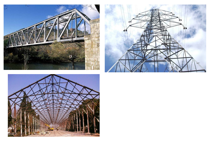
Triangulated structures: are those made by bars,
usually made of steal, joined together in the form of triangles.
Examples: power towers, bridges,
cranes, roofs...
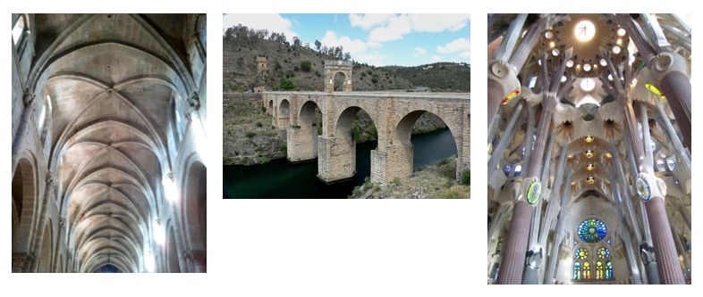
Vaulted structures: are those made or archs,
vaults and domes.
Examples: cathedrals, roman
bridges...
Suspension structures: are those which are
supported by cables or chains.
Examples: bridges, roofs...

Types of stress
What is a stress?
Depending on the way forces are applied over an object it
can be deformed in different ways: became longer, shorter, bend, twist...
We call stress to the effort that the object must
resist so that it does not break.
Tensión
stress: appears
in an object which is being stretched. As a result the object becames longer.

Compression
stress: appears
in an object that is being squeezed. As a result the object becomes shorter.

Bending
stress: appears
in an object subjected to a load applied perpendicularly to it. As a result the
object bends.

Torsion
stress: appears
in an object that is being twisted.

Shear
stress:
appears in an object when two forces tend to cut it. As a result one part of
the object slides over the other.

Buckling
stress: it
only appears in long and thin objects that are squeezed. As a result the object
bends perpendicularly to the direction of the forces.

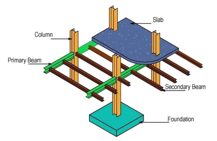
Important parts in structures
Parts of a frame structure:
- Foundations.
- Columns.
- Beams.
- Slab.
Parts of a vaulted
structure:
- Archs.
- Vaults.
- Domes.

Parts of a suspension structure:
- Cables.
- Towers.
- Anchorages.
- Deck.

Forces and loads
·
A
force is an action that causes an object to move or to change its shape.
·
A
load is any force that acts over a structure.

Types of loads
There are different types of loads
acting over the structures:
q Static loads: are those that do not
change over time (or change very little).
-
The
weight of the structure (dead loads).
-
The
weight of persons, furniture, vehicles... (live loads).
q Dynamic loads: are those that change very
quickly. They usually have their origin in nature.
-
Wind loads.
-
Snow loads.
-
Earthquake loads.

The three characteristics that a
structure must fulfil
As we explained at the begining of the
unit a structure must fulfill three characteristics:
- Resistance and rigidity: depend on the
materials used and on the way they are fixed.
- Stability: depends on the position of the center
of gravity of the structure.

II. MECHANISMS
Types of mechanisms

I. THE LEVER
The lever and its parts
A lever is a mechanism consisting of a beam that rotates around a fulcrum. Its different parts are:
- The beam: a rigid part on which the load is paced.
- The fulcrum (or hinge): the part around which the beam rotates.
- The load: which is the weight of the object to be lifted.
- The effort: which is the force exerted in order to lift the load.
- The load arm: distance from the load to the fulcrum.
- The effort arm: distance from the effort to the fulcrum.

Types of lever


Law of the lever

Problem: What effort is it necessary to lift a load of 250N with the following lever?

The law of the lever must be applied:
E x EA = L x LA
E x 2 = 250 x 3;
E = 250 x 3 : 2 = 375N
Note: depending on the length of the effort arm and the load arm the effort needed to lift a load will be bigger or smaller than the load.
Weight of an object
The weight of an object is the force with which the Earth attracts that object towards its center. It can be calculated using the following formula:

Note: the value of g represents the accelaration with which any objects falls down in a given planet, satellite, star... Of course, if an object is placed over the surface of the Moon, Jupiter o Mars the value of g will change (Moon: g=1,62; Jupiter: 24,79; Mars: 3,71). However, in this subject only objects that are placed over the Earth will be studied.
Problem: What effort is it necessary to lift a load of 30kg with the following lever?

w = 30 x 9,8 = 294N
Finally, the law of the lever can be applied just as in the example before:
E x EA = L x LA
E x 7 = 294 x 2;
E = 294 x 2 : 7 = 82N
II.II GEARS AND GEAR TRAINS


II.II GEARS AND GEAR TRAINS
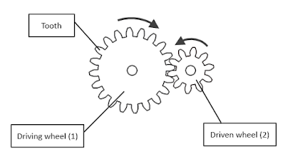
Parts of a gear
One gear
is
formed by two toothed wheels. The driving wheel (1), which
is
connected to the motor, and the
driven wheel (2), which
receives the rotatory movement.


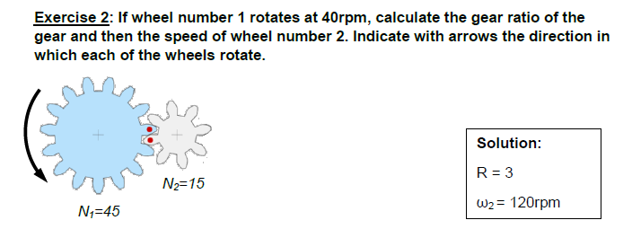
Gear ratio
The gear ratio of a
gear (R) indicates which of the wheels in a gear spins faster. It can be
calculated using both the rotatory speed or the number of teeth:

- If R > 1 driven wheel rotates faster than driving wheel.
- If R < 1 driven wheel rotates slower than driving wheel.
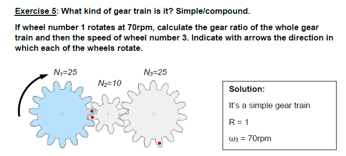
Gear trains
A
gear train is
a mechanical system formed by more than
two
toothed wheels that engage each other.

The gear ratio in a simple gear train can be calculated as:

The gear ratio in a compound gear train can be calculated as:

Exercises with solutions:


No hay comentarios:
Publicar un comentario