WORK FOR THE DAYS FROM THE 9th TO THE 29th OF MAY
(JUST 3rd-ESO B)
(JUST 3rd-ESO B)
The tasks for the next weeks are very related to the SketchUp design that you should have already sent me. In case you haven't, please do it as soon as possible or you won't be able to continue with the new exercises.
Each of you will have to create a word, power point, pdf or similar document with the following information:
1) A little explanation of the ideas suggested by your group in class (2 o 3 lines for each idea) at the beginning of the term. Remember I asked you to think of at least three small objects that you could design to meet a need of your daily life.
2) The decision matrix you did in class with your group. In case you don't remember, a decision matrix is a way to decide which idea is the best according to several criteria.
If your final design (the one you've done in SketchUp) was not one of the options that you considered at that time you should include it now. Remember, the decission matrix was something like this:
If your final design (the one you've done in SketchUp) was not one of the options that you considered at that time you should include it now. Remember, the decission matrix was something like this:

The weight represents the importance each of the criteria has according to you and the sum of all the weights needs to be 100%. Then each idea must be ranked from 1 (very bad) to 5 (very good) for each of the items. In the last row of the table you need to calculate the mark of each idea.
The best idea will be the one that gets the best mark. You will need to create a table and fill it properly in your document
Example: imagine I've given the following weights to each criteria and idea number 1 has been graded like this.
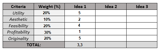
The final mark of the idea has been calculated as a weighted average, like this:
5 x 0,2 + 2 x 0,1 + 4 x 0,2 +1 x 0,3 +5 x 0,2 = 3,3
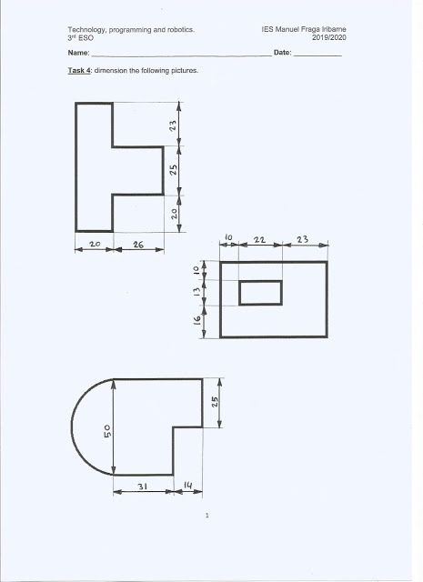
3) Then you'll have to dimension your SketchUp design with the tool that is surrounded in the picture:
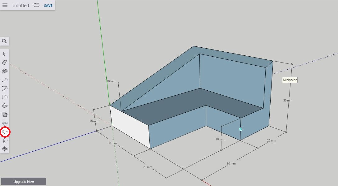
If your piece is too complex you won't need to dimension each of its sides, just the most important ones to give an idea of how big it is aproximately.
Once you've dimensioned it you can take a perspective picture of it and paste it in your document. A good way to do it is by exporting a PNG file:

4) Finally you need to take a picture from each of the views that we studied in the first term: front, side and top. To do it open the Views section of the Right menu of the program (surrounded in red in the picture below):

It is very important to select the parallel projection before you take the pictures:

After that select the different views:

And take one picture of each. Finally you will need to place them as we explained in the technical drawing unit:

Try to paste the three pictures correctly so that the sides of the different views stay aligned.
5) The last thing you need to do is to export your design as an STL file, as explained below:

The STL format is a kind of file specially designed for 3D printing.
6) Once you've added everything to your document you will have to send me an email with two files attached:
- The word / powerpoint / pdf document.
- The STL file of your design.
The deadline is may the 29th.
If you have any question you can ask me by email.
_________________________________________________________________________________
- Instructions for SketchUP:
For those who need to do the retake exam of the first term:
You can also download the solutions step by step:
- https://drive.google.com/open?id=12M4O2fiOQ3TBg3BLlL2CVqPa4N96ARpM
- https://drive.google.com/open?id=12M4O2fiOQ3TBg3BLlL2CVqPa4N96ARpM
________________________________________________
WORK FOR THE DAYS FROM THE 14th TO THE 29th OF APRIL (JUST 3rd-ESO B)


WORK FOR THE DAYS FROM THE 26th OF MARCH TO THE 2nd OF APRIL
What is your homework for the next two weeks?
You are going to continue with the project about 3D printing.
- The first step (if you did it in class skip this part) is to think about an object that could help you some way in your daily life (example: a mobile phone holder). The only requirement is that it dimensions can't exceed 50x50x50mm. That means the object should fit in a cube like this:
- The second step is the one you are going to carry out during the next two weeks: you will have to design that object in a 3D-CAD program.
To do so we are going to use SketchUp which is a CAD program, similar to the one we used in the first term but much easier to manage. There is a free online version of this prgram that you can use without any limit of time. You can also download the program for free, but just for 15 days.
As it is not going to be possible for you to work together in groups with your partners, each of you will make one design of the object your group ahs decided to develop.
You are going to have two weeks to do it, the death line is wednesday the 29th of april. After that you will have to send me your project as I explain at the end.
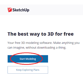
How to enter the online version of SketchUp?
Then Start modeling:

Use your gmail account or any other email to register:

Select the millimeters template:


These are the tools you will need to design your object:

The following tutorial explains, in less than 20 minutes, how to use all the tools you will need:
IMPORTANT!
1) Your objects need to have a certain thickness, their parts can not be completely flat. The best way to do that is by using the tool push/pull:
As an example...
- This object is okey:

- While this one is not okey:

2)Try not to build walls thinner than 2 millimeters in your objects. It's difficult for the 3D printer to print very little details so eventhough it might be able to print 1 mm walls it is not recommended as the piece will not be resistant enough.

3) Try to desing something that solves a real problem. Just as an example I let you two links to new that might give you an idea of a little 3D printed object that could became really useful during the COVID-19 crisis.
How to send your project once it's finished?
Click in the folder:

Then in download:

And select the 2017 version:

Finally attach the file an email with your name, explain briefly the function of the object you've designed and send it to: ivan.carbajo.profesor@gmail.com (just for 3rd ESO-B).
________________________________________________
WORK FOR THE DAYS FROM THE 26th OF MARCH TO THE 2nd OF APRIL
To continue with the contents of this term this week your work will be related with 3D printing technologies. As an introduction you must watch this video:
The different 3D printing applications that appear at the end of the video can help you to complete the second part of the scheme (3D printing applications).
Then you must search in the Internet some of the materials that are commonly used for 3D printing. There are a lot, so finding 5 or 6 is enough. With the information found you'll have to fill in the first part of the scheme (Printing materials).
Finally watch this three videos that talk about 3 of the most used printing techniques. They will help you complete the thirt part of the scheme (Printing techonologies):
- Fused Deposition Modeling (FDM): usually used to print thermoplastics.
- Stereolitrography: used to print with thermosets.
- Selective Laser Melting (SLM): usually used to print metalic materials.
You can download the scheme in the next link:
https://drive.google.com/open?id=15Kt-fjDMAJL6jXuzxy-zzK4AFLfpM5TB

The death line for this task is the 2nd of april (included). In this case the only way to send the work will be by email to ivan.carbajo.profesor@gmail.com.
________________________________________________
https://drive.google.com/open?id=15Kt-fjDMAJL6jXuzxy-zzK4AFLfpM5TB

The death line for this task is the 2nd of april (included). In this case the only way to send the work will be by email to ivan.carbajo.profesor@gmail.com.
________________________________________________
WORK FOR THE DAYS FROM THE 12th TO THE 25th OF MARCH.
This third term the subject of technology will consist in two main blocks:
1) A project about 3D design and printing: whose guide is also in this blog and that will continue after these two weeks.
2) A unit about plastics and some theory aspects of the 3D printing process.
As it is not going to be possible to continue with the project while you stay at home your work for this period will be related to the plastics unit. You have to complete two schemes that you can download in the links below.
You have two options:
a) Download the schemes and complete them using a text editor (Word, for example), save the changes and then upload them to the Virtual Platform (Plataforma Virtual).
b) Download the schemes, print them, complete them by hand and finally scan them to upload them to the virtual platform.
- Plastics classificacion:

- Types of plastics:

This video should be a great help for the second scheme as it explains the different types of themoplastics you need to know.
For the rest of the information you will need to search on the Internet where you will easily find: what thermoplastics, thermosets and elastomers are... properties of different plastics... objects made with each different kind of plastic...
Death line to deliver the work:
- The first scheme (Plastics classification) should be uploaded to the platform by the 19th of march.
- The second (Types of plastics) should be uploaded by the 25th of march.
This work will of course be considered for the final mark of the term.
If you have any doubt or problem with the activity contact me by the institutional email (ivan.carbajo@educa.madrid.org) o by my personal email. If you were not able to upload the schemes to the Virtual Platform you can also send it to me by email, indicating your name and the level (3rd of ESO).
________________________________________________
UNIT 3: PLASTICS AND 3D PRINTING.


_________________________________________________________________________________
PROJECT: 3D DESIGN AND PRINTING.
The goals of this project are:
1) To design and print an object that meets a need for real life.
2) To create a blog to explain the whole process from the desing to the execution of the project.
Design and printing process.
A) Create a Google Drive Shared folder for the group. All the files created during the project must be saved there so that the rest of the members of the group can continue working if some of them is missing.

B) Each group will think of at least three different ideas for the project.
C) Then the group will have to decide which of the ideas is the best with the help of a decision matrix as the one of the image.

The weight assigned to each of the criteria will be a decision of the whole group, that will decide which aspects they consider more relevant. The sum of all the weights must always be 100% and each idea will be ranked from 1 (very bad) to 5 (very good).
D) Design the object in the 3D-CAD program SketchUp.
 |
| SketchUp logo. |

IMPORTANT!
- Select the milimeters template (not meters!).
- Save the project in the project folder in Google Drive as a .skp file each day before the class ends.
________________________________________________
E) Export the design to a .stl file from SketchUp and save it in the project folder in Google Drive.
F) Create the .gcode file with the slicing program Repetier-Host using the following values for the printing parameters:
1) Infill density: 35%.
2) Support type: just in case it is necessary.
3) Overhang angle: 50º.
4) Temperature:
- Plastic: 210ºC.
- Bed: 50ºC.
5) Print speed: 50mm/s.
6) Shell thickness: 1mm.
7) Support patern: grid.
8) Retraction:
- Distance: 3mm.
- Speed: 35mm/s.
Then save the .gcode file both in the project folder in Google Drive and in the SD card of the 3D printer.
G) Print the object:
- Remove the bed of the 3D printer.
- Put adhesive lacquer on the bed.
- Introduce the SD card.
- Turn the 3D printer on.
- Select the file from the SD card.
There will also be a link to the SketchUp project (.skp) saved in the folder of Google Drive to let anybody interested in the project download the design.
C) Publish the blog and send an e-mail with its web adress and the names of the students to the teacher to evaluate the project.
________________________________________________


Examples:
- The voltage of a current is equal to 10 volts (Abbreviated form: V = 10V).
- The intensity of a current is equal to 3 amperes (Abbreviated form: I = 3A).
In order to create an electrc current a current source is required. The most common electric current sources are batteries.
A battery is a component that pushes electrons through a wire by giving them some energy. The higher the voltage of the battery the higher the energy that the electrons will receive.
Electrical circuits.
An electrical circuit consists in several electrical components interconnected in such a way that the electric current can leave the battery and return to it. Some of the most common electrical components and its symbols are:

There are two basic ways to connect the electrical components of a circuit:

If both types of circuit are mixed we get a series-parallel circuit:

Electrical resistance.
The electrical resistance (R) of an electrical component is the opposition of that component to the flow of electric current. It is measured in ohms (Ω). All the electric components have a certain electrical resistance, but we will assume that batteries, wires and switches do not have any resistance. For example, a typical bulb has an electrical resistance of around 800Ω and a small motor of around 30Ω.
The higher the electrical resistance of the components of a wire the lowest the intensity will be because the opposition to the flow of electric current will be higher.
The Ohm's Law.
The relation between voltage, intensity and resistance between two points of an electrical circuit is given by the Ohm's Law.

The Ohm's law allows us to calculate the intensity, the voltage or the resistance in all the components of a circuit. We just need to consider that:
- In a series circuit the components are connected one after the other. In this case the intensity (amount of electrons) through all of them is exactly the same. The voltage will depend on the value of the resistance of each component.
- In a parallel circuit the components are connected one with each other. In this case the voltage (energy lost in each of the components) will be exactly the same. The intensity will depend on the value of the resistance of each component.
 Equivalent resistance.
In order to calculate the intensity that leaves the battery of an electrical circuit the first step is to calculate the equivalent tesistance of the circuit.
The equivalent resistance (Req) of a circuit is the value of resistance that can replace the whole combination of resistances of all the components of that circuit.
The way to calculate the equivalent resistance of a circuit is not the same in a series than in a parallel circuit:


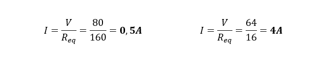
Once the equivalent resistance is known, the intensity that leaves the battery can be calculated applying the Ohm's Law:
 If a series-parallel circuit is being analized the way to calculate the equivalent resistance will be different from one circuit to another. Several steps will be necessary to gather resistances that are connected in series or in parallel.
Example:


Electrical power and electrical energy.
The electrical power (P) of an electrical components measures how fast that component transforms the electrical energy of the current into a different kind of energy. The unit of power in the Internation System of Units is the watt (W).
There are three ways to calculate the electrical power of a component:
a) If the voltage and the intensity are known:

b) If the intensity and its resistance are known:

c) If the voltage and its resistance are known:

The electrical energy spend by an electrical component depends on how much time it has been connected. The unit of energy in the International System of Units is the Joule (J).
The way to calculate it is:

Electrical circuits exercises for the exam.
In the following exercises the voltage and intensity of each component as well as its power and the energy spent in a certain time must be calculated applying the Ohm's Law as explained in class.


PROJECT: DESIGN OF THE ELECTRICAL INSTALLATION OF A HOUSE (USING MULTISIM).

Each device must be connected to a switch that allows to turn it on and off. When the switch that is enxt to a component is closed electric current starts flowing through it, so it turns on.
Besides, fuses will be added to:
- Each of the circuits.
- The whole circuit (general fuse).
A fuse is an electrical component that limits the intensity that can flow through a wire. If intensity exceeds a certain value, that depends on the fuse, it will blow up, opening the circuit and not allowing electric current to flow.
Typical values for the maximum intensity admited by the fuses are:
- CIRCUIT 1: 1A
- CIRCUIT 2: 15A
- CIRCUIT 3: 5A
- CIRCUIT 4: 15A
2) Open a LibreOffice document (that each group must save until the project ends, NOT IN THE DESKTOP!), write the names of all the students of the group and paste an image of the circuit amde in multisim. Then copy and paste the following questions and answer them.
a) What ammeters change their value if the switch of one of the lamps is closed (while the rest of the switches are opened)?
b) And if the switch of the oven is closed as well?
c) What is the value of intensity through a lamp when its switch is closed? And the value of intensity through the toaster? Which one is bigger? Why?
d) What intensity goes through the circuit number 3 if only the oven is connected? And if the ceramic hob is connected as well?
e) Imagine you are at home, with two lamps, the dish washer and the toaster connected. How many amperes is the whole installation using (check the ammeter nesxt to the battery)? What is the value in each of the ammeters of each circuit? What is the relation between the number of amperes in each circuit and the total number of amperes that leave the battery?
f) Is it possible to blow the fuse of any circuit by connecting all the devices at the same time?
g) Is it possible to blow the general fuse? Why is it?
h) Imagine a short circuit occurs in the oven (see image). What fuses would blow up in that case?


Task 2: Draw the following pieces in FreeCad by adding solid cubes and cylinders with the appropiate dimensions and placement. It is also necessary to use the union, intersection and cut tools.


F) Create the .gcode file with the slicing program Repetier-Host using the following values for the printing parameters:
 |
| Repetier-Host logo. |
 |
| Slicing program for 3D printing. |
1) Infill density: 35%.
2) Support type: just in case it is necessary.
3) Overhang angle: 50º.
4) Temperature:
- Plastic: 210ºC.
- Bed: 50ºC.
5) Print speed: 50mm/s.
6) Shell thickness: 1mm.
7) Support patern: grid.
8) Retraction:
- Distance: 3mm.
- Speed: 35mm/s.
Then save the .gcode file both in the project folder in Google Drive and in the SD card of the 3D printer.
G) Print the object:
- Remove the bed of the 3D printer.
- Put adhesive lacquer on the bed.
- Introduce the SD card.
- Turn the 3D printer on.
- Select the file from the SD card.
Guide to make the blog.
A) Use a gmail account (just one for each group) to access blogger.com and create a new blog.
B) The blog will consist of four pages (no posts!), one for each phase of the project:
 |
| How to add a new page to the blog. |
And a menu to easily access all the different pages of the blog (the teacher will explain how to do it in class).
 |
| Example of a blog menu. |
- FIRST PAGE (Development of the idea): in this page the different ideas suggested by the group will be explained. Then an image of the decision matris will be uploaded to justify which idea is the best and therefore has been chosen for the rest of the project.
- SECOND PAGE (Planning of the project): this page will include a Gantt Chart (made online in the web Tom's Planner) in which will be represented how much time the group spects to spend in each phase. The project should take 10 - 12 days of class.
- THIRD PAGE (3D Design): images of the three main views (front, top and side) of the object will be pasted in this page, as well as a perspective image of the object,a s shown bellow:
 |
| Perspective, front, side and top view of an object. |
There will also be a link to the SketchUp project (.skp) saved in the folder of Google Drive to let anybody interested in the project download the design.
- FORTH PAGE (3D printing): in this page the different steps of the printing process will be explained. Several images with the values selected for the parameters will also be included (as the one bellow), as well as the printing time (how much time will it take the printer to print the piece) and the meters of plastic spent.
 |
| Printing parameters. |
Finnaly two more links will be added, one to the .stl file and anoterh to the .gcode file as well as a picture of the object once it has been printed, will also be added to this page.
C) Publish the blog and send an e-mail with its web adress and the names of the students to the teacher to evaluate the project.
________________________________________________
UNIT 2: ELECTRICITY AND ELECTRONIC CIRCUITS.
Electricity.
The universe is made of atoms. All the different atoms thath have been discovered so far (more than 100) appear in the periodic table of elements. All kinds of atoms are made up of three different types of particles: protons, neutrons and electrons.

There is a property of matter (just as colour or hardness) that is closely related to electricity called electric charge. The electric charge of a particle can only take two values: positive or negative.
Electricity are all those phenomena that involve the movement of particles with electric charge. There are several examples of electrical phenomena:
- Rays.
- Static electricity.
- Electric current.
- Electromagnetic waves.

 |
| Different kinds of electrica phenomena. |
Electric currents.
An electric current is a flow of electric charges (mainly electrons) through an electrical conductor. For a material to be considered a good electrical conductor it must have a property called electrical conductivity.
An electric current is a flow of electric charges (mainly electrons) through an electrical conductor. For a material to be considered a good electrical conductor it must have a property called electrical conductivity.
Metals suchs us copper, aluminium, steel, silver or gold are the most frequently used electrical conductors because of their high electrical conductivity. On the opposite, materials with a low electrical conductivity are called electrical insulators. The most commonly used examples are plastics and glass.
 |
| Different types of wire made with different metals (copper, steel and gold). |
Both electric and water currents have many things in common. In an electric current electrons move through a wire, while in a water current it is water molecules that travell through a pipeline or canal. in both cases the currents can be large or small.

There are two aspects that must be considered when describing an electric current:
1) The amount of electrons it carries is called intensity (I) and is measured in amperes (A). One ampere is equal to aproximately 624000000000000000000 (6,24x10^24) electrons per second flowing through the wire.
2) The energy of the electrons that flow is called voltage (V) and is measured in volts (V, as well).
Some typical values of voltage an intensity are:

Examples:
- The voltage of a current is equal to 10 volts (Abbreviated form: V = 10V).
- The intensity of a current is equal to 3 amperes (Abbreviated form: I = 3A).
In order to create an electrc current a current source is required. The most common electric current sources are batteries.
A battery is a component that pushes electrons through a wire by giving them some energy. The higher the voltage of the battery the higher the energy that the electrons will receive.
 |
| Different types of battery. |
Electrical circuits.
An electrical circuit consists in several electrical components interconnected in such a way that the electric current can leave the battery and return to it. Some of the most common electrical components and its symbols are:

There are two basic ways to connect the electrical components of a circuit:

If both types of circuit are mixed we get a series-parallel circuit:

Electrical resistance.
The electrical resistance (R) of an electrical component is the opposition of that component to the flow of electric current. It is measured in ohms (Ω). All the electric components have a certain electrical resistance, but we will assume that batteries, wires and switches do not have any resistance. For example, a typical bulb has an electrical resistance of around 800Ω and a small motor of around 30Ω.
The higher the electrical resistance of the components of a wire the lowest the intensity will be because the opposition to the flow of electric current will be higher.
The Ohm's Law.
The relation between voltage, intensity and resistance between two points of an electrical circuit is given by the Ohm's Law.

The Ohm's law allows us to calculate the intensity, the voltage or the resistance in all the components of a circuit. We just need to consider that:
- In a series circuit the components are connected one after the other. In this case the intensity (amount of electrons) through all of them is exactly the same. The voltage will depend on the value of the resistance of each component.
- In a parallel circuit the components are connected one with each other. In this case the voltage (energy lost in each of the components) will be exactly the same. The intensity will depend on the value of the resistance of each component.

In order to calculate the intensity that leaves the battery of an electrical circuit the first step is to calculate the equivalent tesistance of the circuit.
The equivalent resistance (Req) of a circuit is the value of resistance that can replace the whole combination of resistances of all the components of that circuit.
The way to calculate the equivalent resistance of a circuit is not the same in a series than in a parallel circuit:


Once the equivalent resistance is known, the intensity that leaves the battery can be calculated applying the Ohm's Law:
Example:

- First step: gather R2 and R3 as in a series circuit:

- Second step: gather R2-3 and R4 as in a parallel circuit:

- Third step: gather R2-3-4 and R1 as in a series circuit:

- Finally, the intensity that leaves the battery is calculated in the same way than before:

Electrical power and electrical energy.
The electrical power (P) of an electrical components measures how fast that component transforms the electrical energy of the current into a different kind of energy. The unit of power in the Internation System of Units is the watt (W).
There are three ways to calculate the electrical power of a component:
a) If the voltage and the intensity are known:
b) If the intensity and its resistance are known:
c) If the voltage and its resistance are known:
The electrical energy spend by an electrical component depends on how much time it has been connected. The unit of energy in the International System of Units is the Joule (J).
The way to calculate it is:
Electrical circuits exercises for the exam.
In the following exercises the voltage and intensity of each component as well as its power and the energy spent in a certain time must be calculated applying the Ohm's Law as explained in class.
____________________________________
For this project the Multisim software will be used: multisim.com
Usually the electrical installatin of a house is divided into 5 different parallel circuits. Each of them covers several parts of the house.
- CIRCUIT 1: used to connect all the lamps of the ceiling.
- CIRCUIT 2: used to connect the fridge and general use sockets (for the toaster for example).
- CIRCUIT 3: used to connect the oven and the ceramic hob.
- CIRCUIT 4: used to connect the washing machine and the dishwasher.
- CIRCUIT 5: used to connect the sockets of the bathroom (will not be included in this project).
Each of the components or home appliances of the installation will be represented as electrical resistances. The value of the resistance of each component depends on a lot of factors, but in this project the following values will be used:

Each device must be connected to a switch that allows to turn it on and off. When the switch that is enxt to a component is closed electric current starts flowing through it, so it turns on.
Besides, fuses will be added to:
- Each of the circuits.
- The whole circuit (general fuse).
A fuse is an electrical component that limits the intensity that can flow through a wire. If intensity exceeds a certain value, that depends on the fuse, it will blow up, opening the circuit and not allowing electric current to flow.
 |
| Symbols of a fuse. |
Typical values for the maximum intensity admited by the fuses are:
- CIRCUIT 1: 1A
- CIRCUIT 2: 15A
- CIRCUIT 3: 5A
- CIRCUIT 4: 15A
 |
| Example of electrical installation with just two circuits. There is always one fuse for each circuit and a general fuse for the whole installation. |
Once the circuit is done in Multisim:
1) Add one ammeter (device to meassure the intensity through a wire) in:
- The wire that is connected to the battery (to measure the total intensity).
- The main wire of each of the four circuits of the installation.
- Next to each device.
a) What ammeters change their value if the switch of one of the lamps is closed (while the rest of the switches are opened)?
b) And if the switch of the oven is closed as well?
c) What is the value of intensity through a lamp when its switch is closed? And the value of intensity through the toaster? Which one is bigger? Why?
d) What intensity goes through the circuit number 3 if only the oven is connected? And if the ceramic hob is connected as well?
e) Imagine you are at home, with two lamps, the dish washer and the toaster connected. How many amperes is the whole installation using (check the ammeter nesxt to the battery)? What is the value in each of the ammeters of each circuit? What is the relation between the number of amperes in each circuit and the total number of amperes that leave the battery?
f) Is it possible to blow the fuse of any circuit by connecting all the devices at the same time?
g) Is it possible to blow the general fuse? Why is it?
h) Imagine a short circuit occurs in the oven (see image). What fuses would blow up in that case?
________________________________________________
UNIT 1: TECHNICAL DRAWING AND CAD.
Solutions of the technical drawing exercises: views and dimensioning.


____________________________________
CAD (COMPUTER ASSISTED DRAWING)
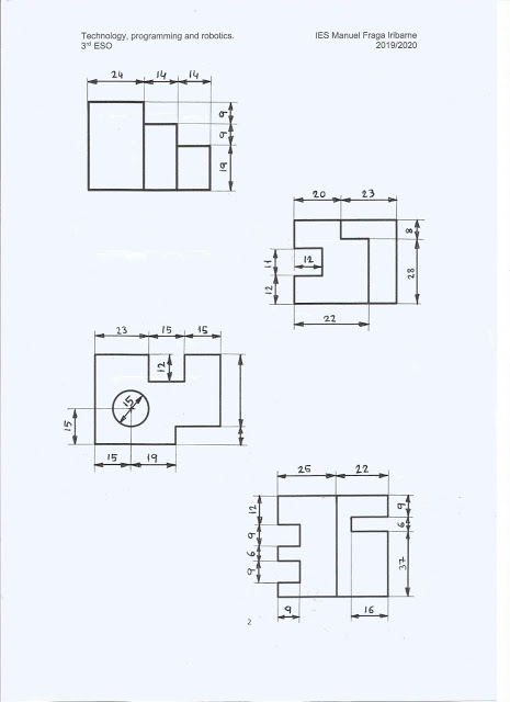
Task 1: draw the following pieces in FreeCad by adding solid cubes and then changing its dimensions and its placement.

 |
| Piece 1. |
 |
| Piece 2. |
 |
| Piece 3. |

 |
| Piece 4. |
 |
| Piece 5. |
Task 3: To design, using FreeCad, a castle/palace inspired by the NeuschWanstein castle located in the state of Bavaria (Germany). At least the following elements should be used: prisms, cylinders, cones and holes.


No hay comentarios:
Publicar un comentario